
Mill Electrical Diagram Ball

AC Technical Diagrams | Original Air Group
Click here to view technical diagram. 1969 Firebird AC Electrical Parts Water Hose (8 Cylinder Engine) Click here to view technical diagram. 197081 Firebird/Camaro/TransAm Use these diagrams with caution and at your own risk as we are not responsible for negligence as a result of use. 197281 Pontiac V8 (301/350/400/455) Compressor Mounting Click here to view technical diagram. 197779 ...


Typical Electrical Drawing Symbols and Conventions.
Basics 19 Instrument Loop Diagram : Basics 1 Plant 1Line . Basics 2 kV OneLine . Basics 3 kV OneLine . Basics 4 600 V OneLine . Basics 5 MCC OneLine . Basics 6 ThreeLine . Basics 7 ThreeLine . Basics 8 MOV Block Diagram Basics 8 MOV Elementary Diagram . Basics 9 Pump Schematic . Basics 10 480 V Pump Block Diagram Basics 10 480 V Pump Schematic . Basics ...


Replacement Parts For Bench Top Mills
Here is a list of the mills for which we have parts diagrams. Bolton XJ9510 Mini Mill. BusyBee CX605 Craftex Mini Mill. BusyBee CX611 Craftex Small Mill. BusyBee CX612 Craftex Mini Mill. Clarke CMD10 Metalworker Micro Mill. Clarke CMD300 Mini Mill. Cummins 7877 Cummins Mini Mill. Eastwood 32498 Mini Mill.


Mills Novelty Co.
Mills Novelty Co. released 671 machines in our database under this trade name, starting in 1896. The 5 most common machines by Mills Novelty Co. owned by VAPS members are (in order): Hi Top, DoReMi, Vest Pocket, Black Cherry Bell, and Bursting Cherry.


Ball Milling method for synthesis of nanomaterials ...
· Steps in ball milling method; 1. As the name suggests, the ball milling method consists of balls and a mill chamber. Therefore over all a ball mill contains a stainless steel container and many small iron, hardened steel, silicon carbide, or tungsten carbide balls are made to rotate inside a mill (drum). 2. The powder of a material is taken inside the steel container. This powder will be made ...


Electronic Projects
Electronic Projects. By Newoldbuilder in Circuits Electronics. 93,218. 22. Suggested Projects. This is a collection of relatively simple electronic projects that I want to build. P.


Powder metallurgy – basics appliions
• In this case, vibratory ball mill is better => here high amount of energy is imparted to the particles and milling is accelerated by vibrating the container • This mill contains an electric motor connected to the shaft of the drum by an elastic coupling. The drum is usually lined with wear resistant material. During operation, 80% of the container is filled with grinding bodies and the ...


Replacement Parts
Here is a list of the machines for which we have parts diagrams. Bolton XJ9510 Mini Mill. BusyBee CX605 Craftex Mini Mill. BusyBee CX611 Craftex Small Mill. BusyBee CX612 Craftex Mini Mill. BusyBee CX704 Craftex Mini Lathe 7x12. Clarke CMD10 Metalworker Micro Mill. Clarke CMD300 Mini Mill. Cummins 5278 Cummins Mini Lathe 7x12.

DESIGN STANDARDS ELECTRICAL SCHEMATIC DIAGRAMS
Electrical diagrams are archived in CDD as HPGL plot files. The process is described below. Native CAD files of ST/CV diagrams are also stored in CDD. ST/EL ELECTRICAL DIAGRAMS A plot file in HPGL2 format is prepared and placed in a subdirectory of the directory SRV4_DIVdrawingsDRAWINGSELECHPGL. This subdirectory, and the plot file it contains, are .


Operations Manuals and Parts Diagrams –
Granite Series Manual and Technical Documents Granite Operations Manual Granite Part Manual(s) Granite Technical Documents Midas 1220/1230 LTD Manual and Technical Documents Midas LTD Operations Manual and Parts Diagram Midas LTD Technical Documents Midas Lathe 1440L and 1337L Manual and Technical Documents MI1440


A Plasma Ball! What is it and How Does it Work? | Science ...
The plasma ball is an electrical apparatus invented by Nikola Tesla in 1894. In the 1980s it gained popularity. It is essentially a glass globe with a central electrode. The globe is filled with a mixture of inert gases. It works just like a teals coil and is useful in conducting electrical experiments. In fact, it can be viewed as a miniature Tesla coil. Inside the ball is a coil of wire that ...

Ball Mill Schematic Diagrams
Ball Mill Schematic Diagram Ball Mill Schematic Diagram. Schematic diagrams for dry ball rotarying circuits grinding mill types, construction, and usage grinding mills the f bond ball mill is a small universal laboratory mill used in calculating the grindability 700 cc ofminus 6 mesh, stage crushed, dry feed.

Measuring high voltage or the "static electricity" on your ...
Crude and simple "field mill" A more precise version of no. 4 above... Build a crude "fieldmill" efield sensor. TO do this, first use a small DC motor to whirl a grounded wire, then place an oscilloscope probe behind the whirling wire so it is alternately shielded and unshielded, mount the entire assembly an inch or so from a large, electrically floating brass ball, then observe the scope ...


ELECTRICAL AND ELECTRONICS DIAGRAMS
Subcommittee 15 Electrical and Electronic Diagrams was formed on April 26, 1964, as a subcommittee of Sectional Committee Yl4Standards for Draw ings and Drafting. When formed, this subcommittee was charged with the responsi bility of preparing a drafting standard covering "electrical schematic, wiring and block diagrams for use in the communiions, electronic, electric power, .


Process Flow Diagram Symbols and Their Usage
· Process flow diagrams use special piping lines to represent how signals are transmitted between equipments. These symbols are used to identify how the instruments in the process connect to each other. And what type of signal is being used. (electrical, pneumatic, data, etc) All lines are fine in relation to process piping lines.


Rectifier Circuits | Diodes and Rectifiers | Electronics ...
Alternative Fullwave Bridge Rectifier Circuit Diagram. Remembering the proper layout of diodes in a fullwave bridge rectifier circuit can often be frustrating to the new student of electronics. I've found that an alternative representation of this circuit is easier both to remember and to comprehend. It's the exact same circuit, except all diodes are drawn in a horizontal attitude, all ...


Ball Mill
The High Energy Ball Mill E max and MM 500 were developed for grinding with the highest energy input. The innovative design of both, the mills and the grinding jars, allows for continuous grinding down to the nano range in the shortest amount of time with only minor warming effects. These ball mills are also suitable for mechano chemistry. Mixer Mills grind and homogenize small sample ...


Omniball® SpringLoaded Contact Options | MillMax Mfg. Corp.
When engaged, the ball compresses and rolls, allowing the mating surfaces to make contact and then easily slide parallel to each other while spring force acts to ensure consistent electrical contact is maintained. This rolling action alleviates the concerns of connector damage such as binding, premature wearing, and structural failure that may occur when using traditional plunger style spring ...


DIY Van Electrical Guide: Build Your Knowledge
ALTERNATOR: None or up to 60A. SHORE: None or up to 80A DC. AC IN: 15A (normal house outlet) INVERTER: None, 1000W, 1500W or 2000W. TRANSFER SWITCH: None. 120V AC Distribution Panel: None (loads are connected directly to the inverter) Choose this diagram if: Your build has modest 120V needs (no device above 1,650W).


Electrical Symbols | Switches and Relays
Electrical diagram software will assist you in drawing your electrical diagrams with minimal effort and makes it very easy for beginners. Electrical symbols and smart connectors help present your electrical drawings, electrical schematic, wiring diagrams and blue prints. Pic. 3. Electrical Symbols — Switches and Relays . Most of the electrical symbols can be changed in their appearance ...

Plasma Ball Experiments – The Wonders of Physics – UW–Madison
Inside the ball is a coil of wires that have electrons going through them oscillating at a very high frequency. This shakes the atoms around the wires so hard that their electrons start to fall off! Inside the glass globe is a partial vacuum. This just means that some of the air has been sucked out. Because there is not as much air in there, it is easier to make electric sparks that can be seen.


Forces and Motion | Forces for Kids | Physical Processes ...
The following forces and motion diagram shows how the ball has moved away from the racquet in a different direction. Similarly, a cricketer or baseball player hits a ball that is moving towards them. The ball then changes direction and moves away from them. Which way the ball goes depends on the direction of the hit. Using an arrow you can show which way a force is moving and how strong it is ...


Ball Mill Components Diagrams
Ball Mill Components Diagrams. Predrawn PID material handling symbols represent ball mill, bulk bag feeder, bulk bag loader, cone crusher, dust collector, hopper, conveyor, grinder, shredder, silo, feeder, filter, wire mesh container, etc. Vector symbols help develop accurate and presentationquality diagrams and documentations.

Clay Processing
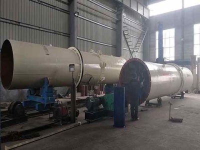
The shredded material then is either dried or ground in a hammer mill. Material exiting the hammer mill is mixed with water and bulk loaded as a slurry for shipping. Figure depicts the process flow for ball clay processing. Indirect rotary or vibrating grate dryers are used to dry ball clay.


What is Electrical Interlocking
A simple electrical interlocking control diagram is shown below. click image to enlarge. Working of Electrical Interlocking. When we push the ON1 button to energies the M1 Contactor (or starts M1 Motor), then circuit complete through Fuse, Overload relay's trip link, OFF Push 1 and ON Push 1. And motor M1 Starts to run. As Contactor M1 energies, it's all normally Close (NC) links open ...
Latest Posts
- تكلفة إنتاج خام الحديد و التقرير
- أفريقيا الذهب طبل مصنع الغسيل للبيع
- المحمولة الصغيرة مصنع لتجهيز المعادن
- متطلبات تدفق المياه آلة الرملي
- صانع المحمولة سحق آلية السيليكا
- كارتون محطم
- بيع معدات سحق المجاميع المحمولة
- كسارة فلوريت المحمول صانع
- قائمة تركيب كسارة الحجر في الهند
- الكوارتز التعدين في ولاية أندرا براديش
- أركنساس البوكسيت معدات التعدين
- ميكرون آلة طحن الحجر
- Tyme القديمة زبدة الجوز آلة طحن
- مليون طن من الحصى المصنع
- مخروط محطم لتأجير كسارات العالم
- Jaw Crusher Motor Fixed Jaw Plate
- Vibrating Feeder Mesh
- Cost Of Stone Crusher And Mills South Africa
- Manufacturing Companies In The Usa
- Chemical Composition Of Cement Ppt
- Rumor Mill Revamped Sonata Due In 2019
- Jaw Crusher Machine Sand Pe
- Jaw Crushers Pdf Jaw Crusherjaw Crushers Pe X
- Coal Coal Pulverizer Mill Size
- Used Mopil Crusher In Uk
- Jaw Crusher Hard Stone Crushing
- Alat Alat Yang Dipakai Di Pertambangan
- Cocunut Oil Grinding Machine
- Tons Per Hour Used Crushing Unit For Sale
- Crushing Anthracite Mining
